

Multi-axis linkage compound machine tool, multi-functional worm grinder, compound worm machine tool
Keywords:
Product Description
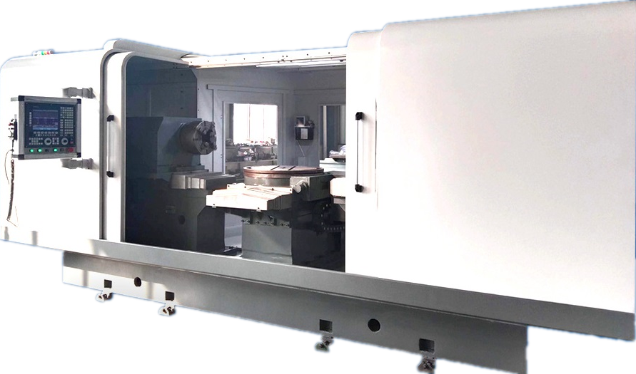
This machine tool is a CNC multi-axis linkage precision compound machine tool with both milling and grinding capabilities. It uses a Fagor 9-axis 5-link CNC system and is equipped with secondarily developed worm gear processing software, making it highly adaptable for various processing applications.
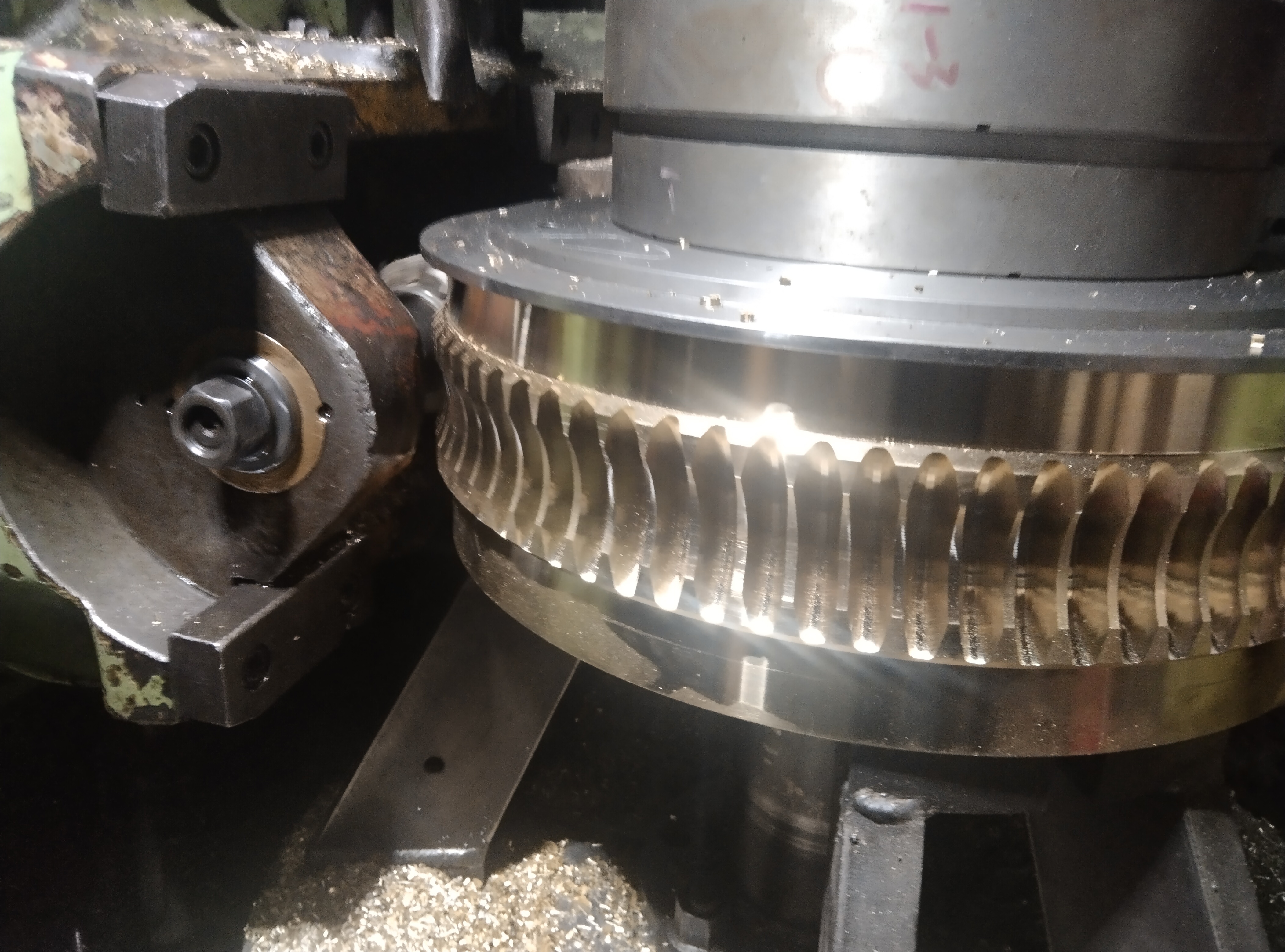
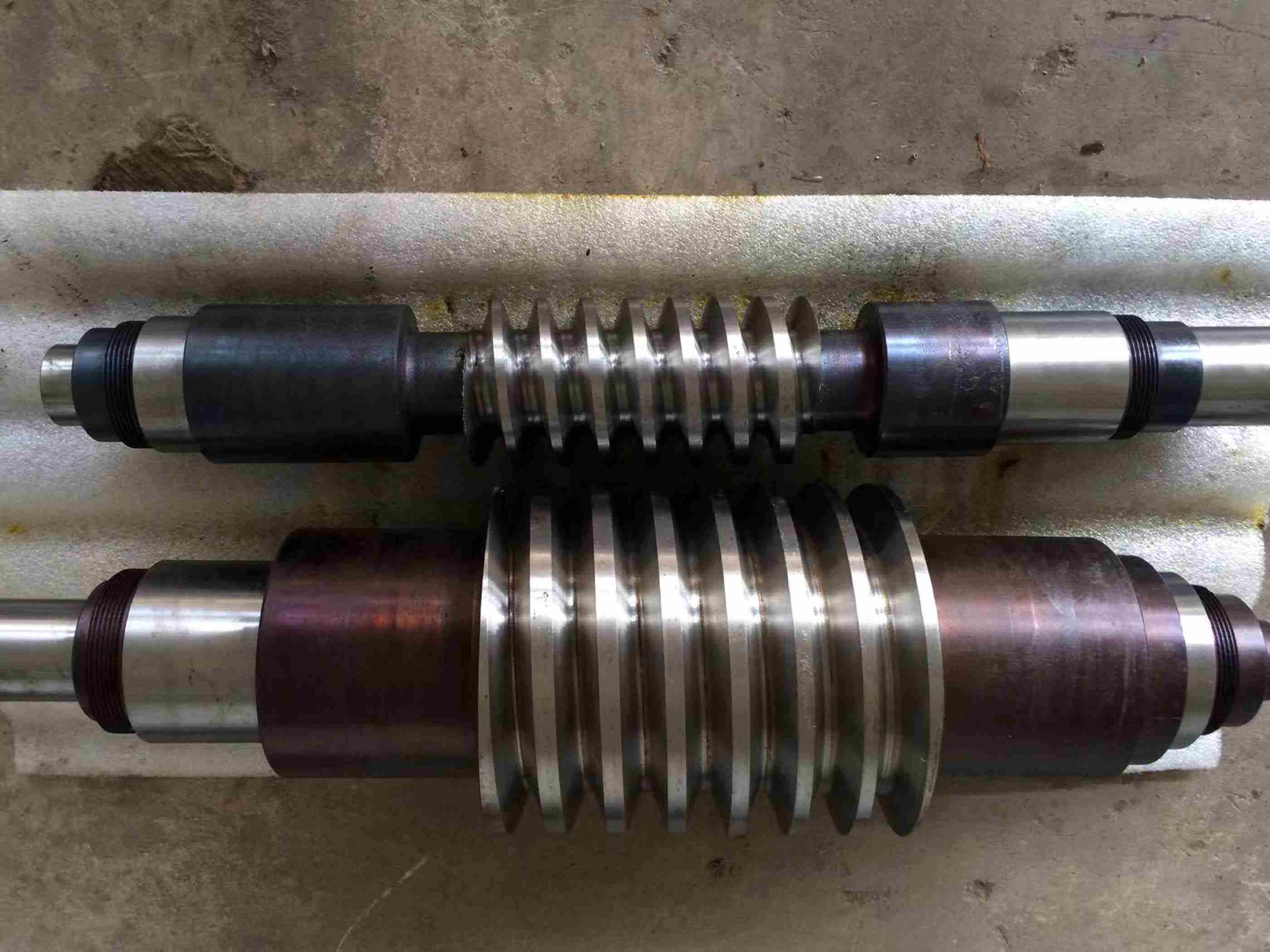
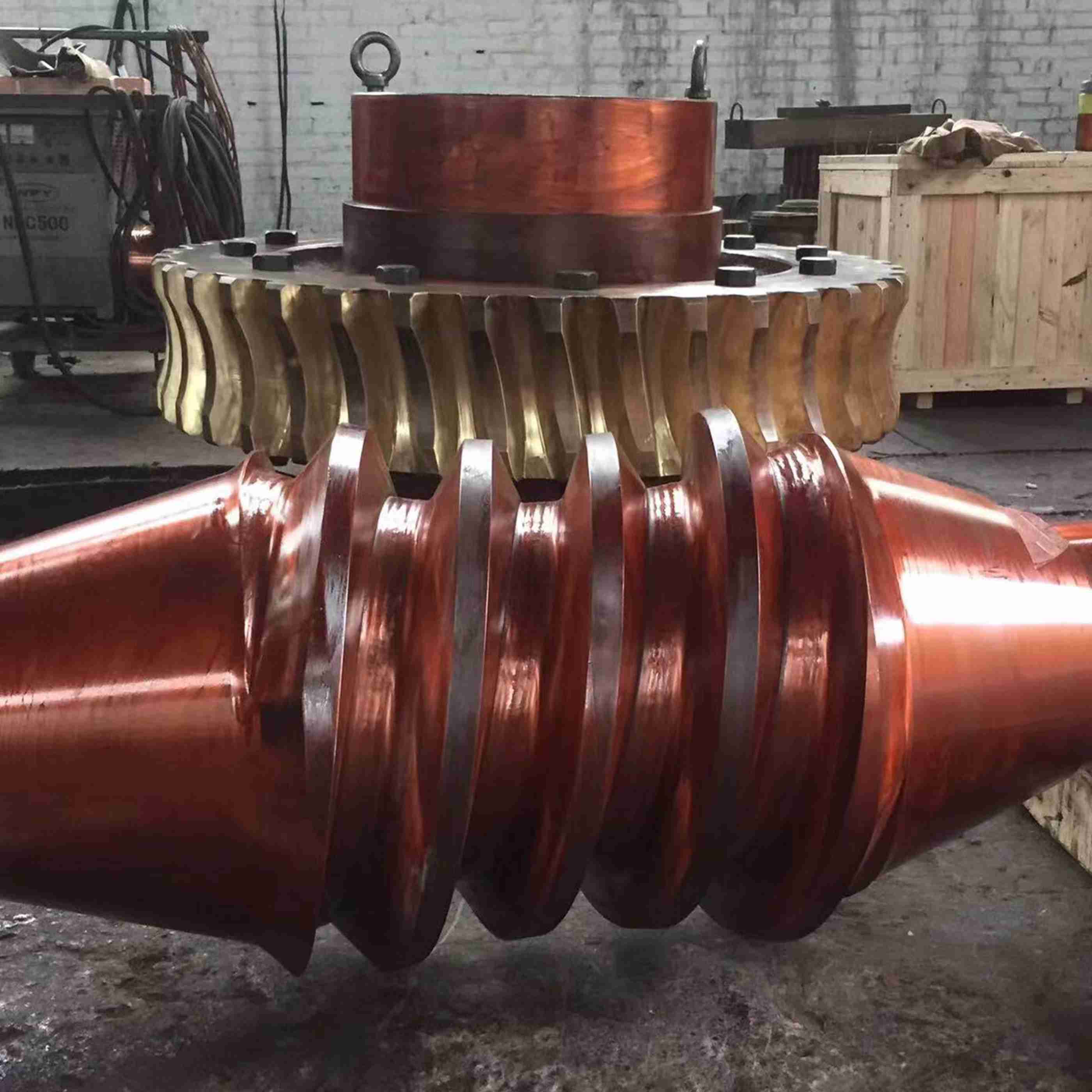
Its main processing range includes: various annular worm gears with a maximum center distance of 350mm, various cylindrical worm gears with a maximum workpiece diameter of 100mm, covering various types such as normal straight-sided worm gears (ZN), axial straight-sided worm gears (ZA), involute worm gears (ZI), conical envelope worm gears (ZK), and circular arc cylindrical worm gears (ZC). In addition, this machine tool can also be used for milling or precision grinding of lead screws and threads, as well as the forming processing of complex parts such as screws, splines, and gears, fully demonstrating its multi-functional compound processing characteristics.
I. Function Introduction:
1. Machine Tool Processing Precision
The machine tool spindle and tool rotary mechanism use a high-precision clearance transmission system with full closed-loop detection and control; the linear motion mechanism uses a high-precision rolling linear guide rail and ball screw transmission, a full closed-loop detection control system, processing micron-level precision.
- Convenient and Quick Adjustment Operation
The machine tool spindle box and tailstock can automatically adjust their positions to quickly adapt to the clamping size requirements of different workpieces; the adjustment and movement of the tool axial position use CNC automatic operation. Only the workpiece positioning size needs to be input, and the tool can accurately move to the processing reference position, achieving quick tool setting. The entire adjustment process is efficient and convenient, greatly improving clamping and tool setting efficiency.
- Grinding Wheel Dressing
This machine has an intelligent grinding wheel dressing function, which can pause the grinding cycle at any position during processing to perform dressing operations. After dressing, the system automatically resumes and continues the grinding process, ensuring processing precision and continuity.
- High Degree of Automation
Using a nine-axis five-link CNC system, all motion axes use CNC automatic movement, with an intelligent machine tool operation human-machine interface, processing platform, and database. By inputting workpiece parameters, the machine tool can achieve automatic tool setting, automatic cycle processing, until the preset cycle processing reaches the set size, the machine tool automatically stops. Coupled with an automatic loading and unloading system, the machine tool can achieve unmanned processing.
5. Processing Types
The machine tool has efficient and high-precision processing capabilities for annular worm gears, cylindrical worm gears (Z1\ZA\ZK\ZN), splines, lead screws, and gears, and other cylindrical transmission components.
6. Structural Layout
This machine tool adopts a scientific layout that conforms to ergonomics, creating an extremely user-friendly operating experience. The innovative high-rigidity, high-precision rotary support structure gives the workpiece and tool rotary system excellent stability and processing precision. The entire machine uses a breakthrough compact design, significantly saving space, and while achieving efficient processing and intelligent automation, it has become a benchmark equipment in the field of small annular worm gear processing. The optimized structural layout brings extraordinary performance, creating excellent value for users.
II. Main Machine Tool Parameters:
Technical Parameters |
Unit |
Annular Worm Gear |
Cylindrical Worm Gear |
Maximum Workpiece Center Distance |
mm |
350
|
|
Minimum Workpiece Center Distance |
|
10 (Conical Envelope)
|
|
Maximum Workpiece Length |
mm |
2000
|
2000
|
Maximum Workpiece Outer Diameter |
mm |
Φ300 |
Φ300 |
Maximum Distance Between Centers |
mm |
2000
|
2000
|
Maximum Grinding Length |
mm |
1600
|
1600
|
Maximum Grinding Depth |
mm |
40
|
40
|
Maximum Module |
mm |
20
|
|
Number of Grindable Screw Threads |
|
1-9 |
Arbitrary |
Workpiece Mother Plane Inclination Angle |
|
±45° |
|
Maximum Helix Angle of Cylindrical Worm Gear |
|
|
±40° |
Maximum Tool Linear Velocity |
(m/s) |
50
|
|
Maximum Workpiece Weight |
Kg |
1000
|
|
Tool Motor Power |
Kw |
32
|
|
Tool Table (B-axis) Rotation Angle
|
|
30° |
|
Machine Center Height
|
mm |
1300
|
|
Tool Table Surface Distance to Workpiece Spindle Center Height |
|
400
|
|
Workpiece Spindle Taper Hole: Morse Taper #5.
|
|
#5 |
|
Maximum Rotation Angle of A-axis
|
|
±95° |
|
Machine Dimensions (Length x Width x Height) |
mm |
|
|
Machine Weight |
Kg |
10000
|
|
III. Machine Tool Structural Type
The machine tool adopts a horizontal structure type. The machine tool components include: bed, workpiece spindle box, tool longitudinal moving slide, tool transverse moving slide, tool rotary worktable, tool radial moving mechanism, tool angle adjustment mechanism, tool power transmission mechanism, grinding wheel dressing mechanism, workpiece tailstock, electrical CNC system, cooling lubrication system, hydraulic system, protective cover, etc.
The workpiece spindle box and all moving parts are set on the longitudinal guide rail of the bed (Z-axis guide rail).
The longitudinal moving slide is set on the Z-axis guide rail, and the tool transverse moving slide, tool rotary worktable, and tool radial feed mechanism are set on it.
The tool angle adjustment mechanism, tool power transmission mechanism, and grinding wheel dressing mechanism are fixed on the tool radial moving mechanism.
The workpiece tailstock is set at the rear end of the Z-axis guide rail.
IV. Numerical Control System
A 9-axis 5-axis linkage CNC system is used, with 9 CNC axes:
(1) C-axis, workpiece main shaft, rotary axis, servo axis;
(2) B-axis, tool table (worktable) rotary axis, servo axis;
(3) X-axis, horizontal feed axis, servo axis
(4) U-axis (X1), radial feed axis, servo axis;
(5) A-axis, tool angle adjustment axis, servo axis;
(6) Z-axis, tool slide axial movement axis, servo axis;
(7) Y-axis, dresser diamond roller vertical movement axis, servo axis;
(8) W (Z1) axis, dresser diamond roller movement axis along the grinding wheel axis, servo axis;
(9) Z2 axis, headstock movement adjustment axis, servo axis.
(10) Tailstock movement axis, virtual axis.
V. Travel of Motion Axes:
1. Z-axis travel distance: 750mm;
2. X-axis travel distance: 400mm (worktable center distance from workpiece main shaft axis 0-400);
3. U (X1) travel distance: 210mm;
4. Y-axis travel: 50mm;
5. W (Z1) axis travel: 35mm;
6. Z2 headstock travel: 400mm.
7. Tailstock travel (virtual axis control): 400mm.
Classification:
Multi-axis linkage compound


